1
2
3
4
5
6
7
8
9
10
11
12
13
14
15
16
17
18
19
20
21
22
23
24
25
26
27
28
29
30
31
32
33
34
35
36
37
38
39
40
41
42
43
44
45
46
47
48
49
50
51
52
53
54
55
56
57
58
59
60
61
62
63
64
65
66
67
68
69
70
71
72
73
74
75
76
77
78
79
80
81
82
83
84
85
86
87
88
89
90
91
92
93
94
95
96
97
98
99
100
101
102
103
104
105
106
107
108
109
110
111
112
113
114
115
116
117
118
119
120
121
122
123
124
125
126
127
128
129
130
131
132
133
134
135
136
137
138
139
140
|
# The Dactyl-ManuForm Keyboard - Python 3
This is a fork of [Dactyl-Manuform](https://github.com/tshort/dactyl-keyboard) by Tom Short, which itself is a fork of [Dactyl](https://github.com/adereth/dactyl-keyboard) by Matthew Adereth, a parameterized, split-hand, concave, columnar, ergonomic keyboard.
The major change is switching to a python based file generator. Both predecessors were exceptional contributions to the ergo keyboard community by the authors but used a rather esoteric programming language, Clojure. My hope is that by converting the code to Python, the community will have an easier time modifying and evolving this design. I am planning to build this keyboard in the next several weeks and will update with my build information and BOM.
I am also planning to create an entirely new object-oriented generator and will add a link when it is complete. In the mean time wanted to add my contribution of a faithful translation of the existing code and general structure into Python. The only geometry addition was an option to add the kalih hot-swap mounting through an STL file.
**The majority of the the rest of the below content is as defined by previous authors, except where noted.**

The main change is that the thumb cluster was adapted from the [ManuForm keyboard](https://github.com/jeffgran/ManuForm) ([geekhack](https://geekhack.org/index.php?topic=46015.0)). The walls were changed to just drop to the floor. The keyboard is paramaterized to allow adjusting the following:
* Rows: 4 - 6
* Columns: 5 and up
* Row curvature
* Column curvature
* Row tilt (tenting)
* Column tilt
* Column offsets
* Height
I built a 4x5 version (40% size) for myself. The default has a bit more tenting than the Dactyl. See the following model files for configurations that may be most common:
* [40% size, (4x5)](https://github.com/tshort/dactyl-keyboard/blob/master/things/right-4x5.stl)
* [60% size, (5x6)](https://github.com/tshort/dactyl-keyboard/blob/master/things/right-5x6.stl)
## Assembly
### Generating a Design - Modified for Python Implementation
**Setting up the Python environment - NEW**
* [Install Python 3.X](https://www.python.org/downloads/release/python-385/) or use your [favorite distro / platform (Anaconda)](https://www.anaconda.com/products/individual)
* It is advisable, but not necessary, to setup a virtual environment to prevent package/library incompatibility
* [Install SolidPython](https://pypi.org/project/solidpython/), easiest method is `pip install solidpython` or `pip3 install solidpython` on linux.
* [Install Numpy](https://pypi.org/project/numpy/), easiest method is `pip install numpy` or `pip3 install numpy` on linux.
* [Install OpenSCAD](http://www.openscad.org/)
**Generating the design - NEW**
* Run `python dactyl_manuform.py` or `python3 dactyl_manuform.py`
* This will regenerate the `things/*.scad` files
* `left_py.scad`
* `right_py.scad`
* `plate_py.scad`
* Use OpenSCAD to open a `.scad` file.
* Make changes to design, repeat run step, OpenSCAD will watch for changes and re-render.
* When done, use OpenSCAD to export STL files
### Printing
Pre-generated STL files are available in the [things/](things/) directory.
When a model is generated, it also generates a `.scad` model for a bottom plate.
This can be exported to a DXF file in OpenSCAD.
The [things/](things/) directory also has DXF files for the bottom plate.
When laser cut, some of the inside cuts will need to be removed.
This model can be tricky to print.
It's wide, so I've had problems with PLA on a Makerbot with edges warping.
This can cause the printer to think its head is jammed.
Even if it successfully prints, warping can cause problems.
On one print, the RJ-9 holder was squished, so I had to cut down my connector to fit.
If printed at Shapeways or other professional shops, I would not expect such problems.
### Thingiverse
[The 4x5 STL left/right pair](https://www.thingiverse.com/thing:2349390) from the [things/](things/) directory is in the thingiverse for public printing
### Wiring
Here are materials I (tshort) used for wiring.
* Two Arduino Pro Micros
* [Heat-set inserts](https://www.mcmaster.com/#94180a331/=16yfrx1)
* [M3 wafer-head screws, 5mm](http://www.metricscrews.us/index.php?main_page=product_info&cPath=155_185&products_id=455)
* [Copper tape](https://www.amazon.com/gp/product/B009KB86BU)
* [#32 magnet wire](https://www.amazon.com/gp/product/B00LV909HI)
* [#30 wire](https://www.amazon.com/gp/product/B00GWFECWO)
* [3-mm cast acrylic](http://www.mcmaster.com/#acrylic/=144mfom)
* [Veroboard stripboard](https://www.amazon.com/gp/product/B008CPVMMU)
* [1N4148 diodes](https://www.amazon.com/gp/product/B00LQPY0Y0)
* [Female RJ-9 connectors](https://www.amazon.com/gp/product/B01HU7BVDU/)
I wired one half using the traditional approach of using the legs of a diode to form the row connections.
(I'm not great at soldering, so this was challenging for me.)
For this side, I used magnet wire to wire columns. That worked okay.
The magnet wire is small enough, it wants to move around, and it's hard to tell if you have a good connection.

For another half, I used stripboard for the row connections.
This allowed me to presolder all of the diodes.
Then, I hot-glued this in place and finished the soldering of the other diode ends.
I like this approach quite a lot.
Connections for the diodes were much easier with one end fixed down.
On this half, I also used copper tape to connect columns.
This worked a bit better than the magnet wire for me.
For a future version, I may try just bare tinned copper wire for columns (something like #20).
With the stripboard, it's pretty easy keeping row and column connections separate.

Note that a telephone handset cable has leads that are reversed, so take this into account when connecting these leads to the controller.
The 3D printed part is the main keyboard.
You can attach a bottom plate with screws.
The case has holes for heat-set inserts designed to hold 3- to 6-mm long M3 screws.
Then, I used wafer-head screws to connect a bottom plate.
If wires aren't dangling, a bottom plate may not be needed.
You need something on the bottom to keep the keyboard from sliding around.
Without a plate, you could use a rubber pad, or you could dip the bottom of the keyboard in PlastiDip.
For more photos of the first complete wiring of v0.4, see [Imgur](http://imgur.com/a/v9eIO).
This is how the rows/columns wire to the keys and the ProMicro
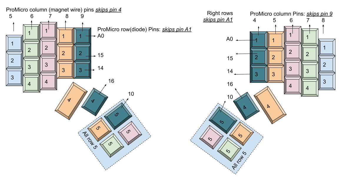
#### Alternative row-driven wiring diagram for ProMicro:
NOTE: you also make sure the firmware is set up correctly (ex: change row pins with col pins)


### Firmware
Firmware goes hand in hand with how you wire the circuit.
I adapted the QMK firmware [here](https://github.com/tshort/qmk_firmware/tree/master/keyboards/dactyl-manuform).
This allows each side to work separately or together.
This site also shows connections for the Arduino Pro Micro controllers.
## License
Copyright © 2015-2020 Matthew Adereth, Tom Short, and Joshua Shreve
The source code for generating the models (everything excluding the [things/](things/) and [resources/](resources/) directories is distributed under the [GNU AFFERO GENERAL PUBLIC LICENSE Version 3](LICENSE). The generated models and PCB designs are distributed under the [Creative Commons Attribution-NonCommercial-ShareAlike License Version 3.0](LICENSE-models).
|
